Average-Value DC-DC Converter Control - MATLAB & Simulink

This example shows how to control the output voltage of a buck-boost converter.
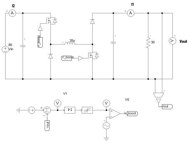
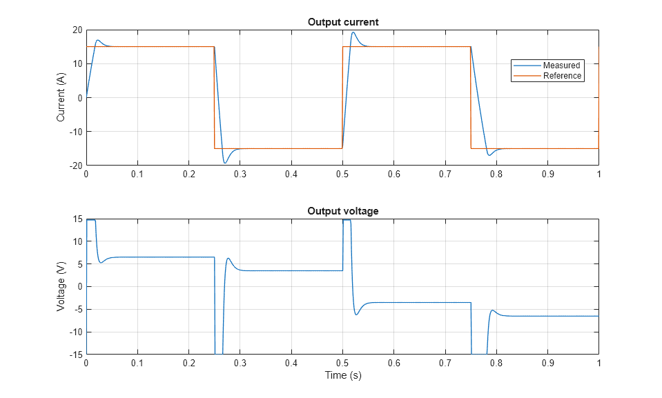
Control the output voltage of a buck-boost converter. To adjust the duty cycle, the Control subsystem uses a PI-based control algorithm. An average-value DC-DC converter model is used to speed up the simulation. The input voltage and the system load are held constant throughout the simulation. The total simulation time (t) is 0.25 s. At t = 0.15 s, the voltage reference changes and the system switches from buck mode to boost mode.
Close loop in H bridge buck boost DC/DC converter using TMS320F28027(c2000 LP), PWM ON/OFF frequently - C2000 microcontrollers forum - C2000™︎ microcontrollers - TI E2E support forums
Average-Value Chopper Control - MATLAB & Simulink
Average-value DC-DC converter - MATLAB
Controller-driven bidirectional DC-DC step-up and step-down voltage regulator - MATLAB

How to Develop DC-DC Converter Control in Simulink - MATLAB & Simulink
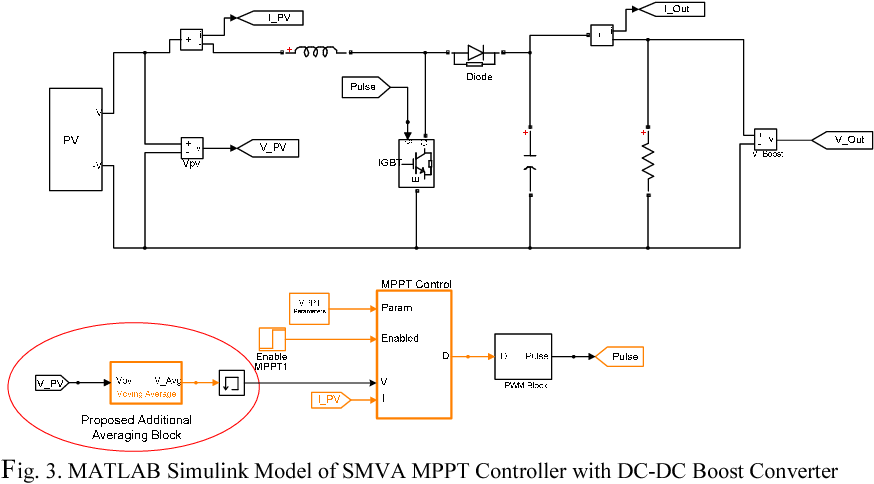
Figure 3 from Implementation of simple moving voltage average technique with direct control incremental conductance method to optimize the efficiency of DC microgrid

Simulink model of a DC-DC converter.

6 kW 45 Vdc Fuel Cell Stack - MATLAB & Simulink

Power Electronics Simulation - MATLAB & Simulink
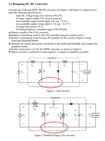
Solved 2.) Designing DC-DC Converter Consider the CUK and